Why Zero-Wobble Imaging Matters
Rigid, vibration-free connections between camera and telescope are the foundation of sharp, high-resolution images. Wobble, flexure, and misalignment blur detail, ruin subframe registration, and waste precious clear sky time. This guide shows practical, hands-on methods to build a rock-solid imaging train.
Expect step-by-step advice on alignment, backfocus, adapters, and mechanical reinforcement. You’ll learn DSLR and mirrorless mounting, dedicated astro camera setups, eyepiece projection options, and filter-wheel integration. Practical photos and diagrams make hardware choices straightforward and repeatable for every setup. Each chapter includes testing, calibration, and troubleshooting workflows so you can eliminate wobble, repeat setups, and capture consistently sharp frames.


Enhancing an Atari Tank Monitor Image: Wobble Fix
Core concepts: alignment, backfocus, and mechanical stability
Optical axis, backfocus, and flange focal distance
The optical axis is the invisible centerline your telescope and camera must share. Backfocus is the distance from the telescope’s focal plane to your camera sensor; flange focal distance (FFD) is the camera mount-specific distance from the lens mount to the sensor (Canon EF ≈ 44mm, Sony E ≈ 18mm). Mismatched or inconsistent distances change effective focal length, vignetting, and whether you can reach focus — especially with corrective flatteners or focal reducers.
Why a rigid, repeatable connection matters
A repeatable, tight mechanical interface preserves collimation and focus between sessions. If you can remove and reattach the camera and regain focus and framing reliably, calibration frames (darks, flats) and star alignment become meaningful. Small shifts multiply: a 0.5 mm axial slip at prime focus can change focus and plate scale at long focal lengths.
Failure modes and visible symptoms
Quick diagnostic checks (actionable)
These checks let you separate optical alignment issues from mechanical instability and guide the reinforcement steps that follow.
Essential tools, adapters, and mounting hardware
Basic adapters and plates
Stock up on the physical building blocks so swapping gear is predictable:
Fasteners, anti-rotation, and fine adjustment
Small parts make or break rigidity. Include:
Materials and tradeoffs
Aluminum is common and low-cost; expect good stiffness for moderate loads. Stainless steel adds durability but weight. Carbon fiber rails or dovetails cut weight and reduce flex—valuable for heavy mirrorless cameras on lightweight mounts. Real-world: swapping an aluminum 20cm dovetail for a carbon one reduced measurable flex by ~0.2–0.4 pixels RMS on a 1200mm scope.
Measurement & safety kit
Mounting DSLR and mirrorless cameras to visual and imaging telescopes
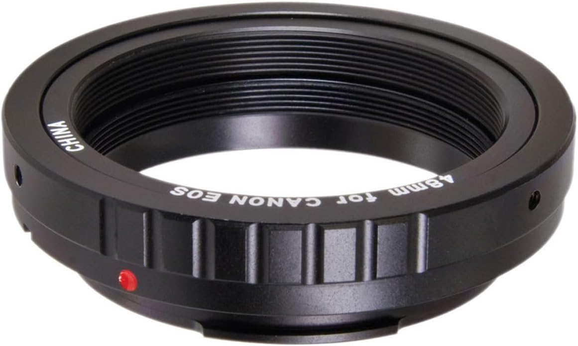
Choosing the right T‑ring and adapter
Pick a camera‑specific T‑ring (Canon EF, Nikon F, Sony E) and a matching nosepiece or T2 adapter that threads to your focuser or camera port. Prefer anodized steel or ISO‑standard T2 parts for repeatable alignment. Example: K&F Concept T‑ring or Baader T‑2 products pair well with Arca plates.
Calculating backfocus and setting extension
Find your telescope’s required camera backfocus (manufacturer spec for flat field) and subtract the camera flange distance. Use spacer tubes or a variable adapter to reach that total without forcing the drawtube.
Mechanical securing and torque sequence
Prime focus, focal reducers, and parfocal setups
Prime focus: minimal spacers give native focal length. Reducers/flatteners require exact backfocus — follow their spec and recheck focus across the field. Parfocal trick: use a short extension or spacer to match eyepiece focus for quick switching (handy for outreach).
Cable management, balance, and mounting patterns
Route USB/remote cables with right‑angle connectors and secure with Velcro near the camera to remove side pull. Heavy cameras shift the center of gravity — counterweight on equatorial mounts or slide the dovetail to rebalance. For equatorial mounts, keep the camera close to the RA axis and use an Arca rail; for alt‑az rigs, aim for symmetric mounting or add a support bracket to prevent pitch/yaw wobble.
Mounting dedicated astronomy cameras and filter wheels
Threaded mating and spacer strategy
Dedicated cooled cameras (ZWO ASI, QHY, Atik) and multi-piece filter wheels commonly use M42/T2, M48 or custom dovetail interfaces. Inspect threads for burrs, hand‑start every connection, and avoid cross‑threading—tighten by hand then a light quarter‑turn. Use precision spacer rings (M48/M42 extenders in 0.5–5 mm steps) to preserve parfocality: for fast scopes and large sensors, aim for repeatable spacing within ±0.2–0.5 mm.
Building a parfocal stack
When stacking camera + filter wheel + reducer/adapter, measure the full optical backfocus and subtract sensor flange to choose spacers. Keep glass filter planes parallel: any tilt shows as stars stretched to one side. Typical practice:
Supporting heavy loads and reducing cantilever
Large cooled bodies and multi-position wheels create cantilever. Use:
Quick tip: a small right‑angle mount between focuser and wheel reduces torque and improves repeatability.
Thermal and cable considerations
Cooled cameras vent heat—avoid blowing it across the optical path (add heat baffles). Secure USB/Power/Guide cables with cable ties or Velcro loops anchored to the tube; use right‑angle and locking connectors to eliminate micro‑movement during long exposures.
Next up: we’ll look at compact imaging options—eyepiece projection and afocal rigs—where the same stiffness principles but smaller form factors come into play.
Eyepiece projection and afocal methods for compact imaging rigs
Compact rigs trade heavy stiffness for portability; eyepiece projection and afocal methods let you squeeze high magnification or a full-field view from small cameras and phones without swapping your main imaging train. Below are practical, hands‑on steps and tips to get repeatable, zero‑wobble results.
Eyepiece projection (camera at the eyepiece focal plane)
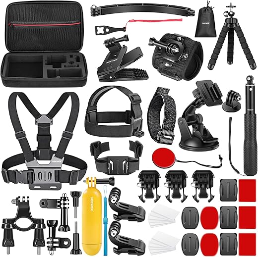
Afocal imaging (camera lens + eyepiece)
Set the scope’s eyepiece to deliver a sharp exit pupil; point the camera lens (focused to infinity) at the eyepiece eyepiece eye‑lens. For phones and small mirrorless cameras, center the optics and minimize lens‑to‑eyepiece offset.

Alignment, vignetting, and rotational play
Quick tip: small mirrorless bodies with an Arca L‑bracket and a sling-style clamp give fast, repeatable mounting with low flex—perfect when you need to pack and go. Next, we’ll cover hands‑on techniques to eliminate remaining wobble and flexure.
Practical techniques to eliminate wobble and flexure
Replace compression‑only adapters with set‑screw collars
Compression rings are convenient but can creep. Swap them for robust set‑screw collars or keyed clamp collars that bite into a flats area on your adapter. A single extra screw or an index pin can reduce rotational play immediately — I’ve seen repeatable guide‑star centroids tighten after this one swap.
Add structural supports and dual‑plate dovetails
Support the camera/rotator/filterwheel stack with a small L‑bracket, rigid support bar, or a dual‑plate dovetail (top and bottom) so torque doesn’t hang on one clamp. Short focusers or stiffening rings under the focuser flange remove cantilevered loads.

Measure flexure with targeted imaging tests
Low‑cost fixes and high‑end upgrades
Trade‑offs: weight, stiffness, and usability
Stiffer = heavier. Expect more counterweight, slower slews, and trickier packing. Aim for the lightest component that reduces measured flexure to within your guiding tolerance — balance stiffness gains against portability and workflow speed.
Testing, calibration, and troubleshooting workflow
Quick verification sequence
Start on the bench, then move to the sky. Perform these tests in order to localize problems efficiently:
How to read the results
Field rotation: whole-frame shear or rotation — suspect rotator/camera flange or off-axis rotator like ZWO/FLI.
Tilt signature: stars sharp on one side, elongated on the other — adaptors, T‑rings (Canon/Nikon/Canon R), or focuser faces need shimming.
Linear drift: smooth drift vector — mount balance, polar alignment, or periodic error.
Sudden jumps: connector/cable tension or loose clamp.
Troubleshooting flowchart (practical)
Maintenance and upgrade cues
Regularly torque-check clamps, clean threads, re-grease focusers (Feather‑Touch/MoonLite), and replace fatigued dovetail screws. Consider professional upgrades (precision rotator, machined flanges, higher‑end focuser) when measured flexure exceeds your target arcseconds and low‑cost fixes plateau.
Now move on to summarizing how to iterate for consistently stable results in the Conclusion.
Build, Test, and Iterate for Stable Results
Understand mechanical and optical interfaces, choose correct adapters and supports, and remove flexure points. Small upgrades—proper brackets, clamp rings, and backfocus-correct adapters—deliver large gains in stability and image fidelity.
Adopt a methodical cycle: measure alignment and flex, modify hardware or spacing, then retest under real conditions. Validate with calibration frames and star tests. Iterate until repeatable. Invest deliberately; consistent, wobble-free imaging rewards patience and pays off in sharper, more reliable results every session.


Wow, that ‘Build, Test, and Iterate’ section is my new mantra.
I’ve been doing afocal shots with my phone and a cheap Eyeskey Universal Smartphone Adapter and was skeptical about ‘zero-wobble’ claims.
The practical techniques for eliminating flex helped a ton — the part about clamping order + testing with a weighted lens hood is GOLD.
Also lol at the author’s aside about ‘astro-duct tape’ 😂 — been there.
Thanks for writing something usable for people who aren’t full-time gear nerds.
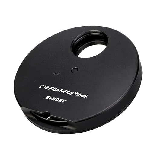
Quick issue: I’m trying to attach a dedicated astronomy camera behind a filter wheel (SVBONY 5-Position 2-inch Filter Wheel with Adapter) and then to a Canon body via T2. The article covered backfocus but my images show obvious tilt on one side — stars look elongated on the left edge.
Could be the filter wheel, the 1.25″ T-Mount, or the SVBONY dovetail alignment. Anyone walked through a step-by-step to isolate tilt vs internal tilt in the filter wheel?
Start by removing pieces: test camera directly on telescope (if possible) to see if tilt persists. Then add the filter wheel alone, check again. If tilt appears after adding the wheel, rotate it 180° and test — some cheap wheels have slight flange misalignment that’s rotationally dependent. Also check the drawtube of the telescope for slop.
I had the same problem — turned out my filter wheel’s adapter was slightly bent. Replaced the adapter ring (cheap fix) and it’s perfect now. If you have a micrometer or dial indicator you can check runout.
And don’t forget about guide scope flex — if you’re dithering between frames the guide could be moving relative to main scope and mimic tilt effects in stacked subs.
One more tip: if the filter wheel has removable adapter plates, try swapping them to see if the tilt stays with the wheel or the adapter. Keeps the troubleshooting methodical.
You can also use a collimation cap or laser to check mechanical alignment before imaging. Makes isolating tilt way faster.
Really enjoyed the mechanical stability section. One nit: when using the SVBONY 5-Position filter wheel, watch out for the combined thickness with a reducer or flattener. I had to add a Variable Extension T2 to reach the right backfocus and it introduced a teeny bit of play until I added a small support bracket under the camera.
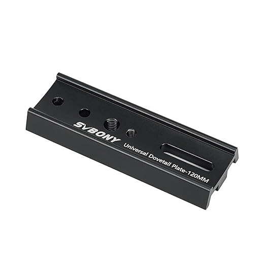
Also the SVBONY 120mm Universal Vixen Dovetail Plate is sturdy but make sure the plane of the plate is perfectly parallel to the focuser tube — shim it if not.
Anyone measured how much sag a 230mm Vixen-Style rail shows under 1.5 kg? Numbers would help.
Good point about the reducer/flattener combo. Sag depends on clamp spacing and rail thickness — on my rail with a single clamp I saw ~0.5mm sag at 1.5kg, but spreading the load with a second clamp reduced it to almost nothing. I’ll try to include measurement methodology in the next update.
I used a small bubble level and a stack of coins as a quick field test — janky but gave me a baseline for before/after mods.
Thanks — adding DIY measurement tips (coins, dial indicator, smartphone level) is a great idea.
If you have access to a dial indicator, mount it to the scope and measure deflection as you add weight at the camera mounting point. Cheap and repeatable.
Good detailed guide but I’d like more on mirrorless specifics — unlike DSLRs, the shorter flange distance changes the adapter stack. The Variable Extension T2 Camera Adapter for Canon helped me get to focus, but I’m still unsure how this interacts with in-camera stacking and focus bracketing.
Is it better to nail zero wobble mechanically and use focus stacking in software, or rely on precise motorized focuser and avoid stacking? Thoughts?
Mirrorless do change the math. Mechanically, always aim for the least amount of adapter complexity — fewer joints = less wobble. If you can get precise focus with a motorized focuser, that’s ideal. Focus stacking is great for planetary or close-ups; for deep-sky it’s usually unnecessary and introduces alignment headaches. So my short answer: prioritize mechanical stability, then use motorized focus for fine control; stack only when it adds something.
I’ve had success combining both: solid mount + motorized focuser for small corrections, then focus stacking for high-magnification targets. But for long-exposure DSO, just mechanical stability + guiding wins.
Short comment: the ‘Testing, calibration, and troubleshooting workflow’ actually works. Ran through the checklist with a 1.25″ T-Mount and it cut my flex in half. Thanks for the stepwise tests! 🙂
Awesome — glad the workflow helped. If you can, post before/after test frames in the comments later; others would benefit from concrete examples.
If you’re still using eyepiece projection with a DSLR like it’s 2005, bless you. 😂
On a serious note: the article nailed the mechanical bits for afocal and eyepiece projection. BUT — pros/cons list for smartphone vs DSLR afocal would be sweet. I love the Eyeskey adapter for quick runs but it’s not exactly precision.
Also, is anyone else paranoid about the 230mm Vixen-Style rail having enough bite on heavier mirrorless bodies? I sometimes add a second clamp just to feel better.
Also consider using a strap or safety cable as a backup when doing public outreach with expensive bodies. Not glamorous but cheap insurance.
I’ll try to include some lightweight printable bracket examples in the follow-up — good suggestion.
Haha — afocal for convenience, DSLR for quality. The Eyeskey is great for outreach but for serious capture you want a rigid camera mount and to avoid the eyepiece as the only support. Doubling clamps on the 230mm rail is a fine workaround; the article suggests centralizing mass to minimize torque.
Paranoid is good. I once had a mirrorless shimmy on a skinny rail — added a short L-bracket to take the weight and solved it.
Agreed — redundancy is underrated. Two clamps + safety tether = peace of mind.
If you can 3D print a small support bracket that joins camera body to focuser housing, do it. Saved me so much stress.
Great read but a note: the 230mm Vixen-Style Dovetail Rail Bar with Slots they list on Amazon has multiple hole patterns — double-check before you buy, I accidentally got the wrong one and it was a pita to return. 😅
Also, small typo in the ‘Core concepts’ section (alignment -> aligment).
Same here — read the item specs carefully. Some sellers bundle a plate that doesn’t match Vixen spacing exactly.
If anyone wants, drop the Amazon links you used and I’ll compare the SKUs to the ones I reference in the article.
Thanks — good catch on both counts. I’ll add a buyer’s checklist for the 230mm rail (hole pattern, slot spacing) and fix the typo in the next pass.
Solid tutorial — finally something that talks about actual mechanical stability instead of just ‘focus and go’.
I’m setting up a Canon DSLR on a SCT and I’m worried about flex between the Sky-Watcher Canon M48 DSLR Camera Adapter and my SVBONY 120mm dovetail. The article’s tips on using the 230mm Vixen-Style Dovetail Rail Bar with Slots seem useful, but does anyone have a simple checklist for torque order and which bolts to tighten first? Also, anyone tried the Variable Extension T2 Camera Adapter for fine backfocus adjustments? Curious if it’s worth having in the bag.
Good question — torque order can make a surprising difference. I usually: 1) secure dovetail to mount, 2) attach camera/adapters to dovetail plate, then 3) tighten any compression rings last. For the Variable Extension T2: great for dialing in backfocus when mixing adapters/filter wheels, but it’s one more point that can introduce wobble unless it’s snug. Use threadlocker on non-moving joints if you won’t change it often.
If you’re using an M48 adapter, check the male/female fit. Some cheap adapters have slightly off-center threads. I replaced one and the wobble vanished. Worth checking before blaming the dovetail or camera.
I had a wobble once from an over-tightened compression ring — sounds counterintuitive but it warped the thin rail a bit. Try a torque wrench or a consistent finger-tight standard. Also shim small gaps with thin aluminum strips if needed.
I appreciated the deep dive into backfocus, but I wish there was a photo showing exact measurements for DSLR + filter wheel + camera adapter combos.
Tried the Sky-Watcher Canon M48 with a 2″ filter wheel and still got focus issues — maybe I’m missing 5-10mm somewhere. Any real-world examples (camera model + adapter stack) that landed perfectly?
I posted my stack measurements in the astronomy subforum for a Canon 80D + SVBONY wheel — PM me and I can share a diagram. Saved me hours of guesswork.
You’re right — hard numbers would help. Off the top of my head: many Canon DSLRs need ~55mm flange focal distance. So if your filter wheel + adapters add up to more than that without a corrective optic, you’ll be out. The Variable Extension T2 can help trim that last few mm. I’ll add a photo table in the next revision.